In this article, we are going to make a cell phone detector circuit that will sense the presence of a cell phone in the surrounding by the detection of these frequencies. A simple cell phone detector circuit can be made in two ways. We will discuss both of the circuits here one by one. As it is said before, the two ways two make a cell phone detector circuit include a combination of Schottky Diode and a Voltage Comparator and a BiCMOS Op-Amp.
How To Make a Mobile Detector Circuit using BiCMOS Op-Amp?
As we know the abstract of our project, let us move ahead and gather some more information to start working on this project. First of all, we will discuss the circuit using BiCMOS Op-Amp.
Step 1: Collecting The Components
The best approach to start any project is to make a list of components and going through a brief study of these components because no one will want to stick in the middle of a project just because of a missing component. A list of components that we are going to use in this project is given below:
Step 2: Studying The Components
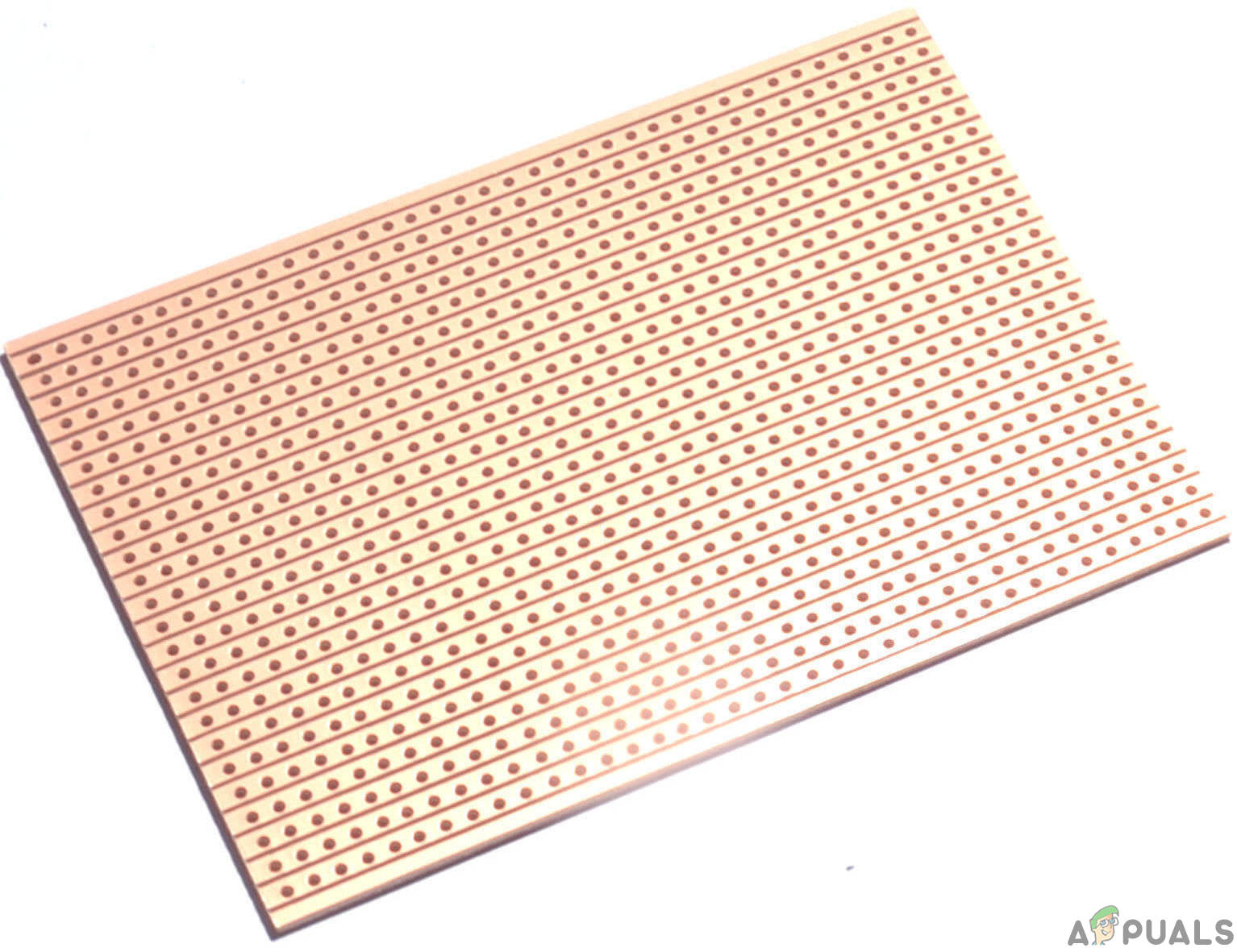
As we now know the main idea behind the project and we also have a complete list of all the components, let us move one step ahead and go through a brief study of all the components. CA3130A and CA3130 are op-amps in which the advantages of both CMOS and bipolar transistors are combined. To provide very high input impedance, very low input current at the input circuit, Gate-protected P-Channel MOSFET (PMOS) transistors are used. this also provides exceptional speed performance. The use of PMOS transistors in the input stage results in common-mode input-voltage capability down to 0.5V below the negative-supply terminal, an important attribute in single-supply applications. The operating supply voltage of a CA3130 series ranges from 5V to 16V. A single external capacitor can be used as a phase compensator with it. For the strobing of the output stage, there is a need for terminal provisions. A BC548 is an NPN transistor. So when the base pin is held at ground, the collector and emitter will be reversed and when the signal is provided to the base the collector and emitter will be forward biased. The gain value of this transistor ranges from 110 to 800. The amplification capacity of the transistor is determined by this gain value. We cannot connect the heavy load to this transistor because the maximum amount of current that can flow through the collector pin is almost 500mA. Current is to be applied to the base pin to bias the transistor, this current (IB) should be limited to 5mA. Antenna: An Antenna is a Transducer. It is used to convert the radio frequencies fields into alternating current or vice versa. There are two main two types of antenna, A transmitting antenna, and a Receiving Antenna, both used for radio transmission. Radio waves are electromagnetic waves that carry signals through the air at the speed of light. The antenna is the most important component in any radio-emitting device. These are used in cellular devices, radar systems, satellite communication, etc. Veroboard is a good choice to make a circuit because the only headache is to place components on Vero-board and just solder them and check the continuity using the Digital Multi Meter. Once the circuit layout is known, cut the board into a reasonable size. For this purpose place the board on the cutting mat and by utilizing a sharp blade (securely) and by taking all the safety precautions, more than once score the load up top and base along the straight edge (5 or multiple times), running over the apertures. After doing so, place the components on the board closely to form a compact circuit and solder the pins according to the circuit connections. In case of any mistake, try to de-solder the connections and solder them again. Finally, check the continuity. Go through the following steps to make a good circuit on a Veroboard.
Step 3: Working Of The Circuit
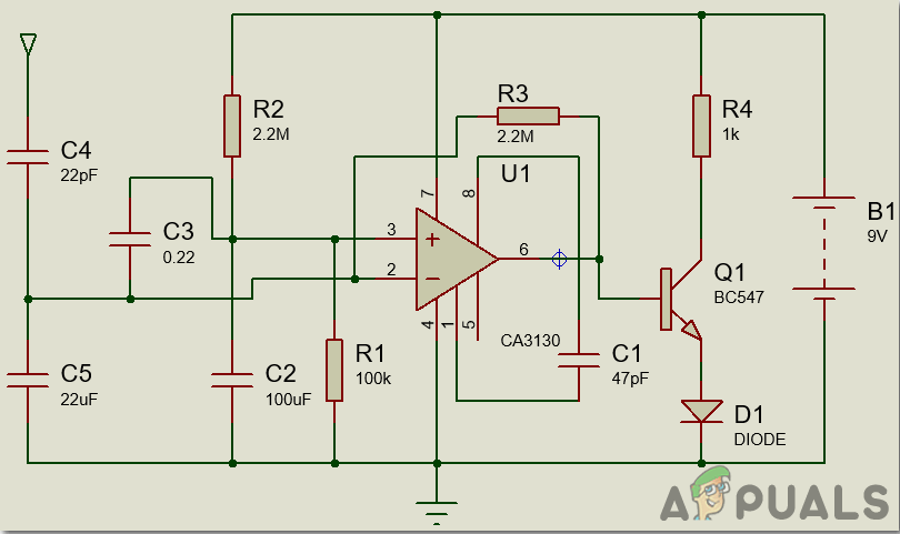
The Op-amp part of the circuit goes about as the RF Signal Detector while the Transistor part of the circuit goes about as the indicator. The capacitors accumulation alongside the receiving wire is utilized to distinguish RF Signals when a mobile phone makes (or gets) a telephone call or sends (or gets) an instant message. Operation Amp peruses the signal by changing over the rise in current at the input to the voltage at the output and the LED will be actuated.
Step 4: Assembling The Components
Now as we know the main working and also the complete circuit of our project, let us move ahead and start making the hardware of our project. One thing must be kept n mind that the circuit must be compact and the components must be placed so close. The circuit will look like the image below:
How To Make a Mobile Detector Circuit using Schottky Diode?
As we have already seen how to make a cell phone detector circuit using a BiCMOS Op-Amp now let us go through another procedure in which we are going to use a combination of Schottky Diode and a Voltage Comparator to make a circuit that will detect a cell phone in the surrounding.
Step 1: Collecting The Components
Following is the complete list of components that will be used to make this configuration.
Step 2: Studying The Components
As we have a complete list of all the components, let us move one step ahead and go through a brief study of all the components. LM339 belongs to those components that have four independent voltage comparators in them. The design of each comparator is in such a way that every comparator can operate on a single power source over a wide range of input voltages. It is also compatible with the split power supplies. The characteristics of some comparators are very unique. For example, Input Common-Mode Voltage Range has a ground included in it when it is operating with a single power supply voltage. The basic purpose of a comparator is that it rotates the signal between digital and analog domains. It takes two inputs at its input terminals and compares them. After comparing, it tells that which is the larger input of the two at the input terminals. It has a wide range of applications. For example, it is used in basic comparator, driving CMOS, driving TTL, low-frequency op-amp, Transducer amplifier, etc. BC547 is an NPN bipolar transistor. The word transistor means Transfer of Resistance, and its basic function is the amplification of the current. BC547 can be used both for switching purposes and amplification purposes. It has three terminals base, emitter, and collector. The amount of current flowing through the collector is controlled by the amount of current flowing through the base to the emitter. The maximum current gain of this transistor is almost 800. For this transistor to operate in the desired region a fixed DC voltage is required. This transistor is biased in such a way that for all the ranges of input, it is always partially biased, for amplification. at the base, the amplification of the input is done and then it is transferred to the emitter side. A Schottky diode is a semiconductor diode formed by the junction of a semiconductor with a metal. The switching action of this diode is very fast. It has a very low forward voltage drop. A current flows in the forward direction when sufficient voltage is applied. the forward voltage of the Schottky diode is from 150-450mV, unlike the other normal diodes whose forward voltage varies from 600-700mV. The better system efficiency and higher switching speed are allowed because of the lower forward voltage.
Step 3: Design Of The Circuit
The design of a circuit mainly consists of three parts, Detector Circuit Design, Amplifier Circuit Design, and Comparator Circuit Design. The detector circuit comprises an inductor, a diode, a capacitor, and a resistor. Here an inductor estimation of 10uH is picked. A Schottky diode BAT54 is picked as the detector diode, which can rectify the low-frequency AC signal. The channel capacitor picked in a 100nF ceramic capacitor used to sift through AC swells. A load resistor of 100 Ohms is utilized. Here, in amplifier circuit design, a simple BJT BC547 is utilized in like common emitter mode. The emitter resistor isn’t required for this situation because the output signal is of low value. The collector resistor’s value is dictated by the estimation of the battery voltage, collector-emitter voltage, and collector current. Typically the battery voltage is chosen to be around 12V. 5V is the operating point voltage of the collector and emitter and the collector current is almost 2mA. Thus as Rc, a 3k-ohm resistor is used. The input resistor should be of large value, almost 100k, because it is used to provide bias to the transistor. This will prevent the flow of the maximum current. Here Lm339 is used in the Comparator Circuit Design. A voltage divider configuration is used to set the reference voltage at the inverting terminal. The reference voltage is set to low the order of 4V because the output voltage from the amplifier circuit is quite low. A resistor of 200-ohm and a potentiometer of 330-ohm is used to achieve this goal. As a current limiting resistor at the output terminal, a 10-ohm resistor is used.
Step 4: Understanding the Mobile Phone Tracking Circuit Operation
The signals that are emitted from a cell phone are Radio-frequency signals. At the point when a cell phone is available close to the circuit, the RF signal from the cell phone is induced into the inductor in the circuit by the process of mutual induction. The Shockley diode is responsible for the amplification of the AC signal of the high frequency of the order of GHz. The capacitor is used to filter the output signal. Now when the mobile phone is brought near this circuit, a voltage is induced into the choke and the diode is used to demodulate the signal. Then the common-emitter transistor amplifies the voltage. Here, the output voltage is more than the reference output voltage. So, the output is a logic high signal which makes the LED glow which will indicate the presence of a cell phone nearby. This is a very simple circuit so it has to be places centimeters away from the circuit.
Step 5: Assembling The Components
The circuit will look like the image shown below:
Applications
There is a wide range of applications of a mobile phone detector circuit. Some of its applications are listed below:
Limitations
There are certain limitations of the above, mobile phone detector circuits.
How To Make A Metal Detector Circuit?How To Make An Intercom Circuit To Exchange Voice Signal Between Two Points?How To Make a Pickpocket Alarm Circuit?How To Make Automated Washroom Light Switch Circuit?