Many curtain opener circuits are available in the market. They are very efficient but very costly. The main aim of this article is to design a circuit that will be used to open or close the curtains just by a press of a button. This solution will be as efficient as the circuit available in the market and will be very low in cost. We will use two ICs and a stepper motor to perform this task.
How To Open And Close The Circuit Automatically?
The heart of this project is two ICs names as CD4013 and ULN2003. These ICs are used with a few more components that are easily available in the market to make a complete circuit. There are two D-type flip-flops which are self governer, located on this CD4013 IC. These flip-flops exist in one of the two states i.e. 0 or 1. The task of these flip-flops is to store information. Both of the modules have a pinout. These pins are names as Data, Clock Input, Set, Reset, and a Couple of output pins.
Step 1: Collecting The Components (Hardware)
The best approach to start any project is to make a list of components and going through a brief study of these components because no one will want to stick in the middle of a project just because of a missing component. A list of components that we are going to use in this project is given below:
Step 2: Gathering The Components (Software)
After downloading the Proteus 8 Professional, design the circuit on it. I have included software simulations here so that it may be convenient for beginners to design the circuit and make appropriate connections on the hardware.
Step 3: Working of a D Flip-Flop
A D-type flip-flop is a flip-flop which has its one input as a DATA input. It is named as Delayed (D) flip flop because when it is given the input at input pin, the data will appear at the output pin after some time when the clock ends. In this way, the data is transferred from the input side to the output side after a required delay. This device is used as a delay device and is also commonly known as a latch. 1-bit binary information is stored in its clock input. The input line controls the flip-flop in this clock. This is used to decide if the data is dropped or recognized. Most o the time, a clock signal is the input. If a Binary High means a logic 1 is sent as a clock input, the flip flop will store the data on the data line. The data input will be simply followed by the normal output, as long as the state of the clock line is HIGH. The data input line will be recognized as soon as the clock line becomes binary low or logic 0. This means that the bit that was previously stored in the flip-flop is retained. When the clock is low, it will be ignored.
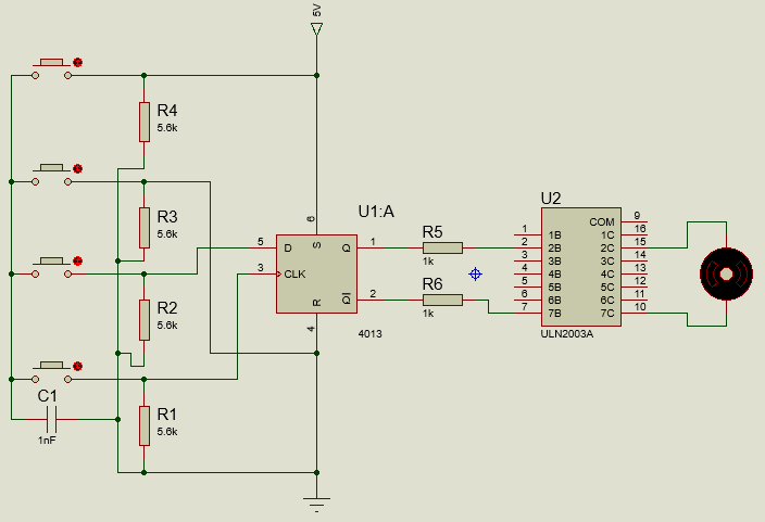
Step 4: Design of the Circuit
CD4013 is an integrated circuit that comes in a 14-pin dual inline package. Its pin1, pin2, pin13, and pin12 all are complementary output but in both of the pairs, one pin is inverse of the other. For example, if [in1 shows 1, then pin2 will show 0. Similarly is the case of the other pair of pin12 and pin13. The Data pins of this IC are pin5 and pin9 and generally, one of the outputs is connected to them. in our circuit pn5 off the IC is connected to the inverting output. Pin3 and Pin11 are named as the clock input of the IC. the D type flip-flop works when these pins receive the input signal to provide the input to these pins, an Astable multivibrator, made by a transistor configuration, can be used or the Logic gates like NOR gate can be used to perform the same task. We are using a transistor to provide the input to these pins. Pin4, Pin6, and Pin8, Pin10 is the set and reset pins of the IC respectively. The output will be received if any one of these pins goes high. For protection, these pins connected to the ground through a resistor of high value. Pin14 is the supply pin of the IC and Pin7 is the ground pin of the IC. The main supply is connected to the pin14 and it should not be greater than 15V. If it is greater than 15V, the IC may burn away. The negative terminal of the battery is connected to the pin7 of the IC. In ULN2003, pin1 to pin7 is the seven input pins of the Darlington configurations. each pin is connected to the base of the transistor and it can be switched just by applying 5V to it. Pin8 is the ground pin of the IC and it is directly connected to the negative terminal of the battery. The test pin of this IC is pin9. pin10 to pin16 are the output pins of this IC.
Step 5: Assembling The Components
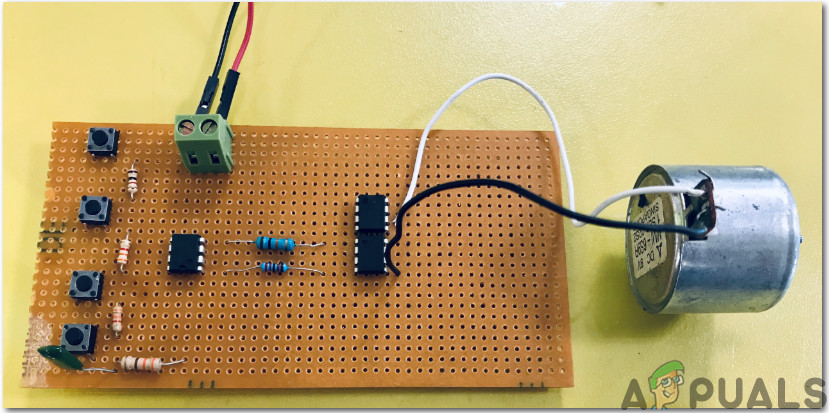
Now, as we know the main connections and also the complete circuit of our project, let us move ahead and start making the hardware of our project. One thing must be kept in mind that the circuit must be compact and the components must be placed so close. The circuit will look like the image below:
Step 6: Circuit Operations
Now as the whole circuit is made, let us test it and see if it operates as required or not. This was the whole procedure to make your curtain open or close automatically. You don’t have to get up and push the curtains Now, you just have to press the buttons by sitting in one place and the curtains will open or close automatically.
How To Make IOT Smart Garage Opener Using Raspberry Pi?How To Make An Intercom Circuit To Exchange Voice Signal Between Two Points?How To Make a Pickpocket Alarm Circuit?How To Make A Cell Phone Detector Circuit?